![]()
Office: 605-368-9007
Toll Free: 888-283-9337
Website: www.rmsroller-grinder.com
RMS Roller Grinder Contact Information
Model and Drive Specs
- Feed Mill Single Pair
- Feed Mill Double Pair
- Feed Mill Triple Pair
- Feed Mill Quad Pair
- Brew Mill Single Pair
- Brew Mill Double Pair
User Guide
Reference Guide
Installation
Additional RMS Equipment
Grain Handling Equipment
General Info
Training and Instruction
• All personnel operating, inspecting, or cleaning this equipment must be properly trained in operation and machine safety. Before operating this equipment, read the operating instructions in the equipment manual. Become thoroughly familiar with the equipment and its controls.
• Maintenance should be done by fully trained and qualified personnel only. On site training directly by RMS is recommended before initial use.
• No maintenance work shall be done on this machine, and no shields shall be removed, until all potential sources of energy are removed and a proper lock-out/tag-out procedure is followed.
General Safety Information
• Appropriate Personal Protective Equipment should be worn at all times, including gloves, hearing protection, and eye protection.
• Noise levels from this equipment can reach as high as 90.5 dB. Hearing protection is recommended when using this equipment.
• When working on or around all equipment, avoid wearing loose clothing, jewelry, unrestrained long hair, or any loose ties, belts, scarves or articles that may be caught in moving parts. Keep all extremities away from moving parts. Entanglement can cause death or severe injury.
• All equipment used in conjunction with this machine or in its proximity shall meet the IEC 61000-6-1 Class A requirements for EMC.
• Usage for other than the recommended application can result in damage to rolls, motors, bearings, and belts and may cause hazards to operators and surrounding machinery.
• A protective earth ground should be installed.
Belt Guards
Belt guards are intended to provide hazard protection for personnel. All guards must be installed on the machine, properly maintained and fully functional. Under no circumstances are these guards to be removed or bypassed. Failure to follow this warning could result in death or severe personal injury.
Ensure that all doors and guards are installed, closed and secured before operating the equipment.
Torque all belt guard hardware to 33 ft/lbs. (44 N-m).
Emergency Stop Buttons
In the event of an emergency situation, press an emergency stop button or remove power from the machine.
Once an emergency stop button has been activated the equipment cannot be restarted until the emergency stop button has been released. This is done by twisting or pulling the center knob to the operational position and pressing the safety reset button.
Safety Labels

Potential pinch point / entanglement hazard between rollers or between rollers and structural components. Follow lockout/tagout procedure before accessing area.

Potential pinch point / entanglement hazard from rotating components. Follow lockout/tagout procedure before accessing area.

Potential contact with magnetic field. Objects made from ferrous materials must not be taken into this area.
Equipment Cleaning
Turn the equipment OFF and disconnect all power sources before removing any belt guards or covers for cleaning purposes. Follow the LOCKOUT/TAGOUT procedure. Failure to follow this warning could result in death or severe personal injury.
It is recommended to maintain regular cleaning schedule of removing covers and vacuuming out of machine on a weekly basis and regular housekeeping of surrounding area on a daily basis to prevent the buildup of explosive levels of dust.
Equipment Disposal
All electrical components are subject to the WEEE directive regarding disposal and should be disposed of in accordance with those requirements.
Feed Mill Single Pair
Storage Conditions: -40F to 140F (-10C to 60C)
Operating Conditions: 0F to 100F (-20C to 40C)
Single Pair Cracker
| Mill Size | Grind Capacity | Mill Size | Grind Capacity | ||
|---|---|---|---|---|---|
| 9x12 | 10-12 Ton/Hr | 12x24 | 30-40 Ton/Hr | ||
| 9x18 | 12-15 Ton/Hr | 12x30 | 40-50 Ton/Hr | ||
| 9x24 | 10-25 Ton/Hr | 12x36 | 70 Ton/Hr | ||
| 9x30 | 25-30 Ton/Hr | 12x42 | 80 Ton/Hr | ||
| 9x36 | 35-40 Ton/Hr | 12x52 | 100 Ton/Hr | ||
| 12x72 | 140 Ton/Hr |
| Mill Size | Belt Size | Belt Tension | Mill Size | Belt Size | Belt Tension | |
|---|---|---|---|---|---|---|
| 9x12 | Qty. 3 AA128 | 3.6 - 3.8 Lbs. | 12x24 | Qty. 4 BB158 | 4.7 - 5.0 Lbs. | |
| 9x18 | Qty. 5 AA128 | 3.2 - 3.4 Lbs. | 12x30 | Qty. 4 BB158 | 4.7 - 5.0 Lbs. | |
| 9x24 | Qty. 5 BB128 | 4.0 - 4.3 Lbs. | 12x36 | Qty. 5 BB155 | 4.7 - 5.0 Lbs. | |
| 9x30 | Qty. 6 BB127 | 4.0 - 4.4 Lbs. | 12x42 | Qty. 8 BB158 | 4.7 - 5.0 Lbs. | |
| 9x36 | Qty. 6 BB127 | 4.7 - 5.0 Lbs. | 12x52 | Qty. 10 BB155 | 4.7 - 5.0 Lbs. | |
| 12x72 | Qty. 12 BB155 | 4.7 - 5.0 Lbs. |
| Bearing Location | Bearing Type |
|---|---|
| Roll Bearings (9x12 - 9x24) | Qty. 4 - 4-Bolt 2-7/16" Ball Bearings |
| Roll Bearings (9x30 - 9x36) | Qty. 4 - 4-Bolt 2-7/16" Roller Bearings |
| Roll Bearings (12x24 - 12x52) | Qty. 4 - 4-Bolt 2-15/16" S2000 Roller Bearings |
| Roll Bearings (12x72) | Qty. 4 - 4-Bolt 3-7/16" S2000 Roller Bearings |
| Idler Bearings | Qty. 2 - 4-Bolt 2-7/16" S2000 Roller Bearings |
| Feed Roll Bearing | Qty. 1 - 4-Bolt 2-7/16" Ball Bearing |
Single Pair Roller Grinder
| Mill Size | Grind Capacity | Mill Size | Grind Capacity | ||
|---|---|---|---|---|---|
| 9x12 | 3 Ton/Hr | 12x24 | 10 Ton/Hr | ||
| 9x18 | 4 Ton/Hr | 12x30 | 12.5 Ton/Hr | ||
| 9x24 | 5.5 Ton/Hr | 12x36 | 15 Ton/Hr | ||
| 9x30 | 7.5 Ton/Hr | 12x42 | 18 Ton/Hr | ||
| 9x36 | 9.5 Ton/Hr | 12x52 | 22 Ton/Hr | ||
| 12x72 | 30 Ton/Hr |
| Mill Size | Belt Size | Belt Tension | Mill Size | Belt Size | Belt Tension | |
|---|---|---|---|---|---|---|
| 9x12 | Qty. 5 AA128 | 3.1 - 3.3 Lbs. | 12x24 | Qty. 6 BB158 | 4.7 - 5.0 Lbs. | |
| 9x18 | Qty. 5 BB130 | 3.8 - 4.0 Lbs. | 12x30 | Qty. 8 BB158 | 4.4 - 4.7 Lbs. | |
| 9x24 | Qty. 5 BB130 | 4.0 - 4.3 Lbs. | 12x36 | Qty. 10 BB158 | 4.7 - 5.0 Lbs. | |
| 9x30 | Qty. 6 BB128 | 4.0 - 4.4 Lbs. | 12x42 | Qty. 12 BB155 | 4.6 - 4.9 Lbs. | |
| 9x36 | Qty. 8 BB128 | 4.1 - 4.4 Lbs. | 12x52 | Qty. 16 BB158 | 4.7 - 5.0 Lbs. | |
| 12x72 | Qty. 16 BB158 | 5.3 - 5.6 Lbs. |
| Bearing Location | Bearing Type |
|---|---|
| Roll Bearings (9x12 - 9x24) | Qty. 4 - 4-Bolt 2-7/16" Ball Bearings |
| Roll Bearings (9x30 - 9x36) | Qty. 4 - 4-Bolt 2-7/16" Roller Bearings |
| Roll Bearings (12x24 - 12x52) | Qty. 4 - 4-Bolt 2-15/16" S2000 Roller Bearings |
| Roll Bearings (12x72) | Qty. 4 - 4-Bolt 3-7/16" S2000 Roller Bearings |
| Idler Bearings | Qty. 2 - 4-Bolt 2-7/16" S2000 Roller Bearings |
| Feed Roll Bearing | Qty. 1 - 4-Bolt 2-7/16" Ball Bearing |
Feed Mill Double Pair
Storage Conditions: -40F to 140F (-10C to 60C)
Operating Conditions: 0F to 100F (-20C to 40C)
| Mill Size | Grind Capacity | Mill Size | Grind Capacity | |
|---|---|---|---|---|
| 9x12 | 3.2 Ton/Hr | 12x24 | 16 Ton/Hr | |
| 9x18 | 6 Ton/Hr | 12x30 | 20 Ton/Hr | |
| 9x24 | 8 Ton/Hr | 12x36 | 24 Ton/Hr | |
| 9x30 | 10 Ton/Hr | 12x42 | 30 Ton/Hr | |
| 9x36 | 12 Ton/Hr | 12x52 | 36 Ton/Hr | |
| 12x72 | 48 Ton/Hr |
| Mill Size | Top Belt Size | Top Belt Tension | Bottom Belt Size | Bottom Belt Tension |
|---|---|---|---|---|
| 9x12 | Qty. 2 5VX1030 | 5.6 - 6.0 Lbs. | Qty. 2 5VX1220 | 5.4 - 5.7 Lbs. |
| 9x18 | Qty. 2 5VX1030 | 7.9 - 8.4 Lbs. | Qty. 2 5VX1220 | 7.4 - 7.9 Lbs. |
| 9x24 | Qty. 2 5VX1030 | 10.0 - 10.6 Lbs. | Qty. 2 5VX1220 | 9.3 - 10.0 Lbs. |
| 9x30 | Qty. 3 5VX1017 | 8.5 - 9.1 Lbs. | Qty. 3 5VX1180 | 8.0 - 8.6 Lbs. |
| 9x36 | Qty. 3 5VX1000 | 10.1 - 10.8 Lbs. | Qty. 3 5VX1180 | 9.4 - 10.0 Lbs. |
| Mill Size | Top Belt Size | Top Belt Tension | Bottom Belt Size | Bottom Belt Tension |
|---|---|---|---|---|
| 12x24 | Qty. 3 5VX1600 | 7.4 - 7.8 Lbs. | Qty. 3 5VX1374 | 7.8 - 8.3 Lbs. |
| 12x30 | Qty. 3 5VX1600 | 9.1 - 9.7 Lbs. | Qty. 3 5VX1374 | 9.7 - 10.3 Lbs. |
| 12x36 | Qty. 3 5VX1600 | 10.9 - 11.7 Lbs. | Qty. 3 5VX1374 | 11.6 - 12.4 Lbs. |
| 12x42 | Qty. 3 5VX1600 | 12.5 - 13.4 Lbs. | Qty. 3 5VX1374 | 13.5 - 14.4 Lbs. |
| 12x52 | Qty. 4 5VX1600 | 11.9 - 12.7 Lbs. | Qty. 4 5VX1400 | 12.6 - 13.5 Lbs. |
| 12x72 | Qty. 5 5VX1600 | 12.4 - 13.2 Lbs. | Qty. 5 5VX1400 | 13.2 - 14.0 Lbs. |
| Bearing Location | Bearing Type |
|---|---|
| Roll Bearings (9x12 - 9x24) | Qty. 8 - 4-Bolt 2-7/16" Ball Bearings |
| Roll Bearings (9x30 - 9x36) | Qty. 8 - 4-Bolt 2-7/16" Roller Bearings |
| Roll Bearings (12x24 - 12x52) | Qty. 8 - 4-Bolt 2-15/16" S2000 Roller Bearings |
| Roll Bearings (12x72) | Qty. 8 - 4-Bolt 3-7/16" S2000 Roller Bearings |
| Feed Roll Bearing | Qty. 1 - 4-Bolt 2-7/16" Ball Bearing |
Feed Mill Triple Pair
Storage Conditions: -40F to 140F (-10C to 60C)
Operating Conditions: 0F to 100F (-20C to 40C)
| Mill Size | Grind Capacity | Mill Size | Grind Capacity | |
|---|---|---|---|---|
| 9x12 | 3.2 Ton/Hr | 12x24 | 16 Ton/Hr | |
| 9x18 | 6 Ton/Hr | 12x30 | 20 Ton/Hr | |
| 9x24 | 8 Ton/Hr | 12x36 | 24 Ton/Hr | |
| 9x30 | 10 Ton/Hr | 12x42 | 30 Ton/Hr | |
| 9x36 | 12 Ton/Hr | 12x52 | 36 Ton/Hr | |
| 12x72 | 48 Ton/Hr |
| Mill Size | Top Belt Size | Top Belt Tension | Middle Belt Size | Middle Belt Tension | Bottom Belt Size | Bottom Belt Tension |
|---|---|---|---|---|---|---|
| 9x12 | Qty. 2 5VX1060 | 5.6 - 6.0 Lbs. | Qty. 2 5VX1220 | 5.4 - 5.7 Lbs. | Qty. 5 BB130 | 3.5 - 3.8 Lbs. |
| 9x18 | Qty. 2 5VX1060 | 7.8 - 8.3 Lbs. | Qty. 2 5VX1180 | 7.5 - 7.9 Lbs. | Qty. 5 BB130 | 3.8 - 4.0 Lbs. |
| 9x24 | Qty. 2 5VX1060 | 10.0 - 10.6 Lbs. | Qty. 2 5VX1220 | 9.4 - 10.0 Lbs. | Qty. 5 BB130 | 4.0 - 4.3 Lbs. |
| 9x30 | Qty. 3 5VX1050 | 8.5 - 9.0 Lbs. | Qty. 3 5VX1180 | 8.0 - 8.6 Lbs. | Qty. 6 BB128 | 4.0 - 4.4 Lbs. |
| 9x36 | Qty. 3 5VX1050 | 9.9 - 10.5 Lbs. | Qty. 3 5VX1180 | 9.4 - 10.0 Lbs. | Qty. 8 BB128 | 4.1 - 4.4 Lbs. |
| Mill Size | Top Belt Size | Top Belt Tension | Middle Belt Size | Middle Belt Tension | Bottom Belt Size | Bottom Belt Tension |
|---|---|---|---|---|---|---|
| 12x24 | Qty. 3 5VX1600 | 10.0 - 10.6 Lbs. | Qty. 3 5VX1400 | 10.6 - 11.3 Lbs. | Qty. 6 BB158 | 4.7 - 5.0 Lbs. |
| 12x30 | Qty. 3 5VX1600 | 12.5 - 13.4 Lbs. | Qty. 3 5VX1400 | 13.4 - 14.3 Lbs. | Qty. 8 BB158 | 4.6 - 4.9 Lbs. |
| 12x36 | Qty. 3 5VX1600 | 10.9 - 11.6 Lbs. | Qty. 3 5VX1400 | 11.6 - 12.4 Lbs. | Qty. 5 BB168 Qty. 5 BB155 | 4.4 - 4.7 Lbs. |
| 12x42 | Qty. 3 5VX1600 | 12.5 - 13.4 Lbs. | Qty. 3 5VX1374 | 13.5 - 14.4 Lbs. | Qty. 12 BB162 | 5.0 - 5.3 Lbs. |
| 12x52 | Qty. 4 5VX1600 | 11.9 - 12.7 Lbs. | Qty. 4 5VX1374 | 12.4 - 13.3 Lbs. | Qty. 16 BB158 | 4.7 - 5.0 Lbs. |
| 12x72 | Qty. 5 5VX1600 | 12.4 - 13.2 Lbs. | Qty. 5 5VX1400 | 12.9 - 13.8 Lbs. | Qty. 20 BB168 | 5.1 - 5.4 Lbs. |
| Bearing Location | Bearing Type |
|---|---|
| Roll Bearings (9x12 - 9x24) | Qty. 12 - 4-Bolt 2-7/16" Ball Bearings |
| Roll Bearings (9x30 - 9x36) | Qty. 12 - 4-Bolt 2-7/16" Roller Bearings |
| Roll Bearings (12x24 - 12x52) | Qty. 12 - 4-Bolt 2-15/16" S2000 Roller Bearings |
| Roll Bearings (12x72) | Qty. 12 - 4-Bolt 3-7/16" S2000 Roller Bearings |
| Idler Bearings | Qty. 2 - 4-Bolt 2-7/16" S2000 Roller Bearings |
| Feed Roll Bearing | Qty. 1 - 4-Bolt 2-7/16" Ball Bearing |
Feed Mill Quad Pair
Storage Conditions: -40F to 140F (-10C to 60C)
Operating Conditions: 0F to 100F (-20C to 40C)
| Mill Size | Grind Capacity | Mill Size | Grind Capacity | |
|---|---|---|---|---|
| 9x12 | 2 Ton/Hr | 12x24 | 11 Ton/Hr | |
| 9x18 | 4 Ton/Hr | 12x30 | 14 Ton/Hr | |
| 9x24 | 5.5 Ton/Hr | 12x36 | 16.5 Ton/Hr | |
| 9x30 | 7 Ton/Hr | 12x42 | 19.5 Ton/Hr | |
| 9x36 | 8.5 Ton/Hr | 12x52 | 25 Ton/Hr | |
| 12x72 | 33.5 Ton/Hr |
| Mill Size | Top Set Belt Size | Top Set Belt Tension | 2nd Set Belt Size | 2nd Set Belt Tension | 3rd Set Belt Size | 3rd Set Belt Tension | Bottom Set Belt Size | Bottom Set Belt Tension |
|---|---|---|---|---|---|---|---|---|
| 9x12 | Qty. 2 5VX1160 | 5.4 - 5.8 Lbs. | Qty. 2 5VX1017 | 5.8 - 6.1 Lbs. | Qty. 2 5VX1180 | 5.5 - 5.8 Lbs. | Qty. 2 5VX978 | 5.8 - 6.2 Lbs. |
| 9x18 | Qty. 2 5VX1220 | 7.3 - 7.8 Lbs. | Qty. 2 5VX1060 | 7.7 - 8.2 Lbs. | Qty. 2 5VX1220 | 7.4 - 7.8 Lbs. | Qty. 2 5VX1060 | 7.7 - 8.2 Lbs. |
| 9x24 | Qty. 2 5VX1220 | 9.3 - 9.9 Lbs. | Qty. 2 5VX1060 | 9.9 - 10.5 Lbs. | Qty. 2 5VX1220 | 9.4 - 10.0 Lbs. | Qty. 2 5VX1060 | 9.8 - 10.4 Lbs. |
| 9x30 | Qty. 3 5VX1180 | 8.0 - 8.5 Lbs. | Qty. 3 5VX1060 | 8.4 - 9.0 Lbs. | Qty. 3 5VX1180 | 7.3 - 7.7 Lbs. | Qty. 3 5VX1030 | 7.5 - 7.9 Lbs. |
| 9x36 | Qty. 3 5VX1180 | 9.4 - 10.0 Lbs. | Qty. 3 5VX1060 | 9.9 - 10.5 Lbs. | Qty. 3 5VX1220 | 8.6 - 9.2 Lbs. | Qty. 3 5VX1030 | 9.1 - 9.7 Lbs. |
| Mill Size | Top Set Belt Size | Top Set Belt Tension | 2nd Set Belt Size | 2nd Set Belt Tension | 3rd Set Belt Size | 3rd Set Belt Tension | Bottom Set Belt Size | Bottom Set Belt Tension |
|---|---|---|---|---|---|---|---|---|
| 12x24 | Qty. 3 5VX1600 | 7.3 - 7.8 Lbs. | Qty. 3 5VX1400 | 7.7 - 8.2 Lbs. | Qty. 3 5VX1600 | 7.2 - 7.6 Lbs. | Qty. 3 5VX1320 | 7.4 - 7.8 Lbs. |
| 12x30 | Qty. 3 5VX1600 | 9.0 - 9.6 Lbs. | Qty. 3 5VX1400 | 9.6 - 10.2 Lbs. | Qty. 3 - 5VX1600 | 8.3 - 8.9 Lbs. | Qty. 3 5VX1400 | 8.6 - 9.2 Lbs. |
| 12x36 | Qty. 3 5VX1600 | 10.8 - 11.5 Lbs. | Qty. 3 5VX1400 | 11.5 - 12.3 Lbs. | Qty. 3 5VX1600 | 10.9 - 11.6 Lbs. | Qty. 3 5VX1374 | 11.5 - 12.3 Lbs. |
| 12x42 | Qty. 3 5VX1600 | 12.5 - 13.4 Lbs. | Qty. 3 5VX1400 | 13.5 - 14.4 Lbs. | Qty. 3 5VX1600 | 11.7 - 12.5 Lbs. | Qty. 3 5VX1320 | 12.4 - 13.3 Lbs. |
| 12x52 | Qty. 4 5VX1600 | 11.9 - 12.7 Lbs. | Qty. 4 5VX1400 | 12.6 - 13.5 Lbs. | Qty. 3 5VX1600 | 11.2 - 11.9 Lbs. | Qty. 4 5VX1320 | 11.8 - 12.6 Lbs. |
| 12x72 | Qty. 5 5VX1600 | 12.4 - 13.2 Lbs. | Qty. 5 5VX1400 | 12.7 - 13.6 Lbs. | Qty. 5 5VX1600 | 11.6 - 12.4 Lbs. | Qty. 5 5VX1400 | 11.6 - 12.4 Lbs. |
| Bearing Location | Bearing Type |
|---|---|
| Roll Bearings (9x12 - 9x24) | Qty. 16 - 4-Bolt 2-7/16" Ball Bearings |
| Roll Bearings (9x30 - 9x36) | Qty. 16 - 4-Bolt 2-7/16" Roller Bearings |
| Roll Bearings (12x24 - 12x52) | Qty. 16 - 4-Bolt 2-15/16" S2000 Roller Bearings |
| Roll Bearings (12x72) | Qty. 16 - 4-Bolt 3-7/16" S2000 Roller Bearings |
| Feed Roll Bearing | Qty. 1 - 4-Bolt 2-7/16" Ball Bearing |
Brew Mill Single Pair
Storage Conditions: -40F to 140F (-10C to 60C)
Operating Conditions: 0F to 100F (-20C to 40C) Indoor Use Only
| Mill Size | Grind Capacity | Overall Dimensions | Approximate Weight |
|---|---|---|---|
| MicroMill | 500 Lbs. /Hr | 22" W x 22" L x 52" T | 225 Lbs. |
| 6x6 | 1,200 Lbs. /Hr | 29" W x 25" L x 56" T | 450 Lbs. |
| 9x6 | 3,000 Lbs. /Hr | 29" W x 56" L x 66" T | 1,200 Lbs. |
| 9x12 | 5,000 Lbs. /Hr | 35" W x 56" L x 66" T | 1,400 Lbs. |
| 9x18 | 10,000 Lbs. /Hr | 41" W x 59" L x 69" T | 1,850 Lbs. |
| Mill Size | Motor HP | Motor Voltage | Motor Amps |
|---|---|---|---|
| MicroMill | 1/3HP | 1 Phase 60Hz - 115/208-230V | 6A/3.3A |
| 6x6 | 1HP | 3 Phase 60Hz//50Hz - 230/406V//190/380V | 3.3/1.6A//3.6/1.8A |
| 6x6 | 2HP | 3 Phase 60Hz//50Hz - 230/406V//190/380V | 5.6/2.8A//6.6/3.3A |
| 9x6 | 3HP | 3 Phase 60Hz//50Hz - 230V/460V//190/380V | 8.2/4.1A//9.6/4.8A |
| 9x12 | 3HP | 3 Phase 60Hz//50Hz - 230V/460V//190/380V | 8.2/4.1A//9.6/4.8A |
| 9x18 | 5HP | 3 Phase 60Hz//50Hz - 230V/460V//190/380V | 13.2/6.6A//15.8/7.9A |
| Mill Size | Belt Size | Belt Tension |
|---|---|---|
| MicroMill | ANSI #50 Chain | N/A |
| 6x6 | N/A | N/A |
| 9x6 | Qty. 2 AA105 | 2.0 - 2.2 Lbs. |
| 9x12 | Qty. 2 AA105 | 2.0 - 2.2 Lbs. |
| 9x18 | Qty. 2 AA105 | 3.0 - 3.2 Lbs. |
| Bearing Location | Bearing Type |
|---|---|
| Roll Bearings (MicroMill) | Qty. 4 - 2-Bolt 1" Ball Bearings |
| Roll Bearings (6x6) | Qty. 3 - 4-Bolt 1-1/4" Ball Bearings |
| Roll Bearings (9x6-9x18) | Qty. 4 - 4-Bolt 2-7/16" Ball Bearings |
| Idler Bearings (9x6-9x18) | Qty. 2 - 1-3/16" Ball Bearing Insert |
Brew Mill Double Pair
Storage Conditions: -40F to 140F (-10C to 60C)
Operating Conditions: 0F to 100F (-20C to 40C) Indoor Use Only
| Mill Size | Grind Capacity | Overall Dimensions | Approximate Weight |
|---|---|---|---|
| 6x6 | 1,200 Lbs. /Hr | 29" W x 25" L x 67" T | 700 Lbs. |
| 9x6 | 3,000 Lbs. /Hr | 29" W x 56" L x 78" T | 1,700 Lbs. |
| 9x12 | 5,000 Lbs. /Hr | 35" W x 56" L x 78" T | 2,300 Lbs. |
| 9x18 | 10,000 Lbs. /Hr | 41" W x 59" L x 81" T | 3,500 Lbs. |
| Mill Size | Motor HP | Motor Voltage | Motor Amps |
|---|---|---|---|
| 6x6 | 1HP | 3 Phase 60Hz//50Hz - 230/406V//190/380V | 3.3/1.6A//3.6/1.8A |
| 6x6 | 2HP | 3 Phase 60Hz//50Hz - 230/406V//190/380V | 5.6/2.8A//6.6/3.3A |
| 9x6 | 3HP | 3 Phase 60Hz//50Hz - 230V/460V//190/380V | 8.2/4.1A//9.6/4.8A |
| 9x12 | 3HP | 3 Phase 60Hz//50Hz - 230V/460V//190/380V | 8.2/4.1A//9.6/4.8A |
| 9x18 | 5HP | 3 Phase 60Hz//50Hz - 230V/460V//190/380V | 13.2/6.6A//15.8/7.9A |
| Mill Size | Top Set Belt Size | Top Set Belt Tension | Bottom Set Belt Size | Bottom Set Belt Tension |
|---|---|---|---|---|
| 6x6 | N/A | N/A | N/A | N/A |
| 9x6 | Qty. 2 5VX800 | 3.1 - 3.3 Lbs. | Qty. 2 5VX978 | 3.0 - 3.2 Lbs. |
| 9x12 | Qty. 2 5VX800 | 3.1 - 3.3 Lbs. | Qty. 2 5VX978 | 3.0 - 3.2 Lbs. |
| 9x18 | Qty. 2 5VX800 | 4.5 - 4.7 Lbs. | Qty. 2 5VX978 | 4.3 - 4.5 Lbs. |
| Bearing Location | Bearing Type |
|---|---|
| Roll Bearings (6x6) | Qty. 6 - 4-Bolt 1-1/4" Ball Bearings |
| Roll Bearings (9x6-9x18) | Qty. 8 - 4-Bolt 2-7/16" Ball Bearings |
Overview
Agriculture Mill Information
Ag mills can be provided with any of the following optional equipment:
- Inlet Hopper
- Gravity Scalper/ Scalper Assist
- Magnet Gate/ Feed Roll
Additional add-ons are also available to automate your machine:
- Roll Gap Automation
- Accugap
- Bearing Monitoring
- Automatic Greasing System
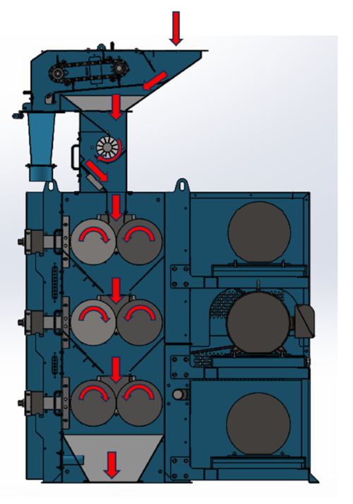
Agriculture Mill Material Flow
The image below shows the flow of material through an ag mill.
Brewery Mill Information
Brewery mills can be provided with any of the following optional equipment:
- Vertical Auger
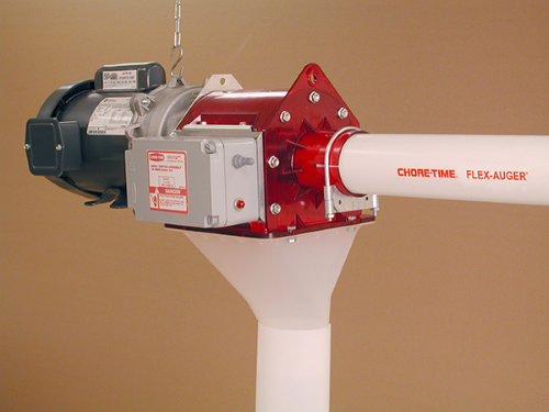
- Flex Auger Discharge Attachment - 45 Degree or Horizontal
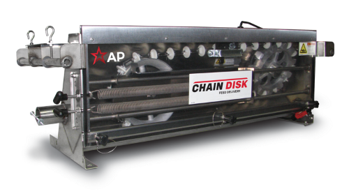
- Chain Disk System Discharge Attachment - 4" or 2-3/8" Diameter
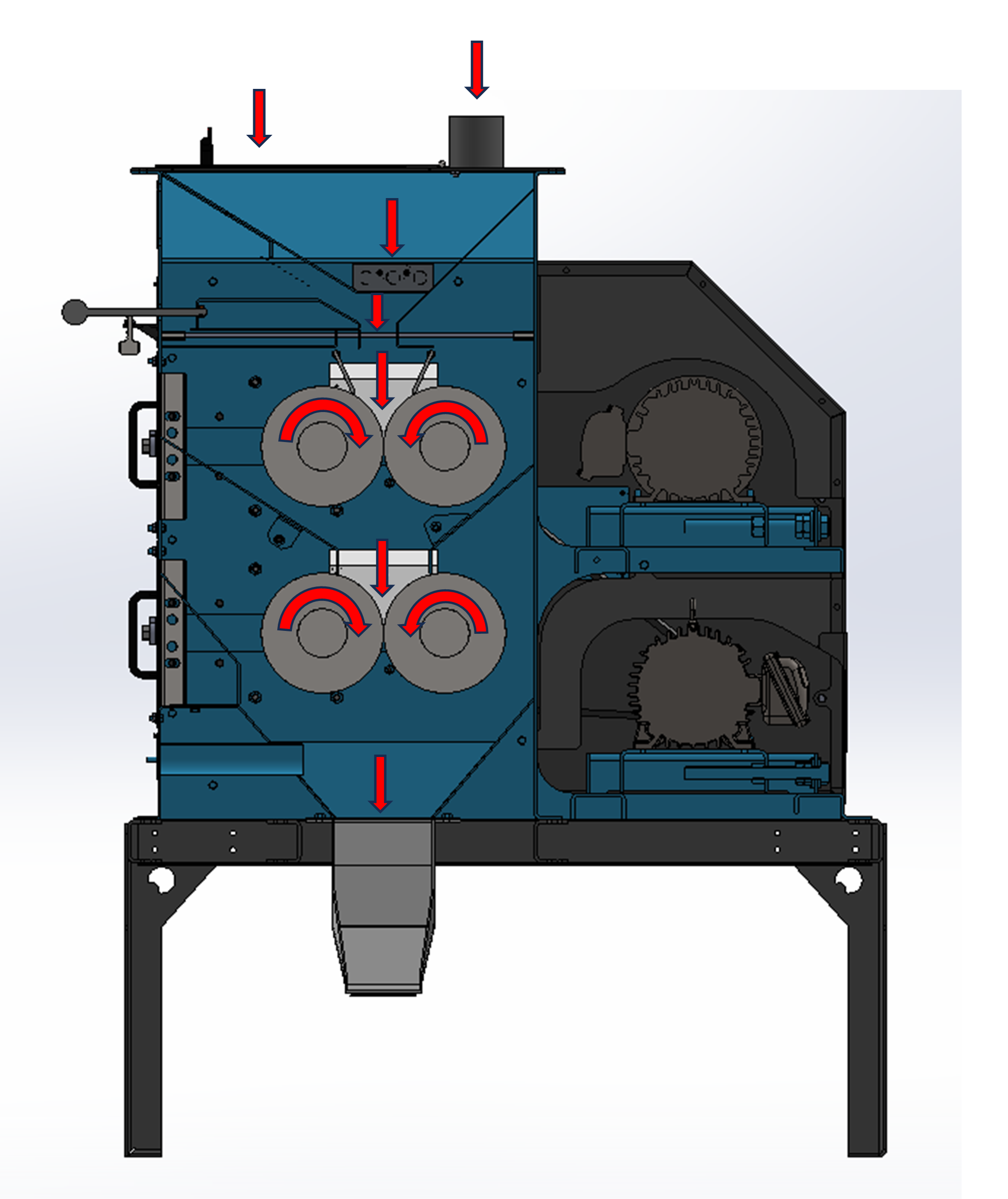
Brewery Mill Material Flow
The image below shows the flow of material through a brewery mill.
Lubrication
Why Greasing is Important
The environment around roller grinder bearings is dirtier than standard bearing conditions.
As such, using a larger amount of grease to frequently purge (over-fill) the bearings helps to flush out contaminants from the inside of the bearing.
While bearings with more grease will run warmer, bearings with contaminants run even hotter and experience much more wear. It is better to replace a depleted grease tube than a bad bearing or the resulting broken roll shaft.
With this in mind, all bearings on all RMS Machines cannot be over-greased.
Any excess grease will purge through the seals on the front and rear of the bearing.
Purge simply means grease is leaking out of the bearing, and it signifies that the bearing is full of grease.
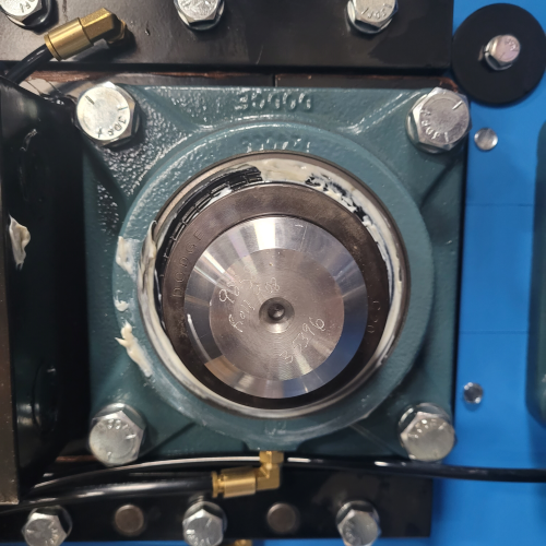
This purging is the best protection against bearing contamination. An example of a correctly lubricated bearing with grease purging around the seal is shown below.
Figure 1. A correctly greased bearing has grease purging around the perimeter.
In dirty environments around roller grinders, the manufacturer recommends frequently greasing the bearings to purge until fresh grease comes out.
Old grease will be discolored or dirty, whereas fresh grease will look nearly identical to what comes out of the tube.
Doing this ensures that your bearing has as little outside contamination as possible. The less foreign material entering your bearing, the better. Refer to the next page for greasing schedule recommendations.
Following this schedule should ensure that your bearings are fully greased. If fresh grease does not purge out of the bearing after 6-8 pumps, continue greasing.
Note: The greasing schedule that is shown below should be used as a basic starting point. All bearings should be monitored closely for temperature and the greasing schedule should be adjusted accordingly.
| Greasing Schedule | ||
|---|---|---|
| Hours Run Time Per Day | Pumps of Grease | Interval |
| 1-8 | 4 | Daily |
| 8-16 | 8 | Daily |
| 16-24 | 12 | Daily |
Purge bearings once every week!
Quick Tips for Greasing
- Grease bearings while the machine is running to ensure grease is evenly spread around the circumference of the bearing.
- Always wipe down grease zerks before greasing. Otherwise, any dirt on the grease zerks will be forced into the bearing.
- Bearings from RMS come greased and ready for operation. Bearings from the manufacturer should be greased until fresh grease comes out.
Other Lubrication Guidelines
- Feed roll bearings do not need to be greased as often as the main bearings that hold the corrugated rolls. Grease feed roll bearings once every month.
- Gearbox lubrication guidelines for feed rolls can be found in the Feed Roll section.
- Motor lubrication guidelines can be found in the Motors section.
Grease Lines
Inspect grease lines prior to greasing to make sure none have “blown out”.
If you notice a blown out grease line, install a grease zerk directly on the bearing and apply (2) pumps of grease.
The bearing may or may not take grease in this case, which is why the grease line blew out.
It is important to monitor the temperature of this bearing until it can be changed, possibly making it to the next roll change.
If the bearing takes grease, measure the blown out line and order a replacement. Replacement parts can be ordered from RMS.
Because of the maximum pressure (PSI) constraints of the RMS grease dispersion system, using a hand-operated grease gun is recommended.
If the use of an automatic or pneumatic grease gun is preferred, then it is necessary to insert a pressure reducing valve in-line between the grease gun and the supply air.
We recommend using an adjustable pressure (PSI) type not to exceed 100 lbs. This valve can be purchased from RMS.
Whether manual or automatic greasing is employed, this action should never replace visual inspection of the greased elements as the primary method of determining its effectiveness.
We recommend the creation of an inspection procedure to be carried out once a month, at a minimum.
This procedure will help aid your maintenance team in the identification and resolution of any problems related to greasing, such as a blown out grease line.
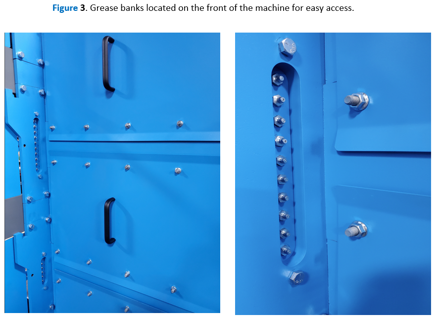
Figure 3. Grease banks located on the front of the machine for easy access
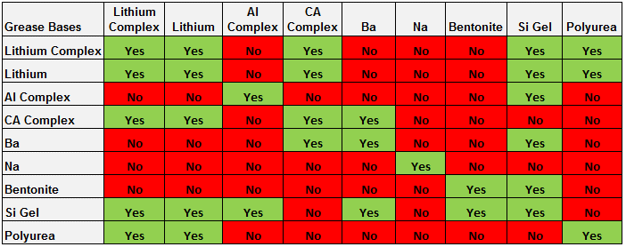
Grease Compatibility
Did you know you can’t mix just any grease with any other grease?
It’s true - doing so can cause catastrophic damage to equipment. And it’s true even if the grease types are the same.
Why is this the case?
Grease consists of two parts - the actual lubricant (normally oil) and a carrier, or base. Each has its own function.
It’s the bases that are not compatible.
Always know the base of the grease you are adding and the base of the grease you are adding to.
Once you know those things, you can use the compatibility chart below. A “Yes” indicates compatibility.
Figure 4. Table showing the compatibility of grease bases
Brew Mill Grease Resource
SuperTac Food Grade H1
NLGI #2
SuperTac Food Grade Grease H1 is an extreme pressure, anti-wear, high temperature, extra tacky grease for use in food, feed and pharmaceutical processing and packaging equipment.
SuperTac Food Grade Grease H1 is made with the highest quality, highly refined and purified non-toxic pure paraffin base technical white, USP grade white oils and polyalphaolefin (PAO) synthetic base fluids available. Further blended into this H-1 grease is an aluminum complex base thickener, adhesive/cohesive additives and food grade anti-microbial agents.
SuperTac Food Grade Grease H1 can be used in the lubrication of ball, roller, journal and sliding bearing applications and chain applications, where there is a chance of incidental contact with food, foodstuffs, drinking water, potable water or ground water may occur.
SuperTac Food Grade Grease H1 is the most waterproof food grade grease we offer. Synthetic Food Grade Grease H1 meets USDA 1998 H1 guidelines and is NSF registered.
Performance Benefits Excellent resistance to acidic compounds. Excellent shear and mechanical stability: grease stays in place, resists separating and running off components. Increased oxidation stability. Protects against rancidity and buildup due to bacterial and fungal growth. High dropping point. Protects against rust and corrosion. Resists emulsifying, washing out and spraying off when exposed to moisture. Contains PTFE for extra protection.
View the Product Data Sheet
View the Saftey Data Sheet
Feed Mill Grease Resource
Blue Gard 500+
NLGI #1, Lithium Complex grease is the recommended lubricant for use in an Automatic Greasing System
NLGI #2, Lithium Complex grease is the recommended lubricant for use in all mills without an Automatic Greasing System
Blue Gard® 500+ is a modern, high-performance, heavy duty, lithium complex multi-purpose grease, that sets a new standard for automotive, industrial and agricultural use. Blue Gard 500+ qualifies for the highest performance level of automotive chassis and wheel-bearing grease classification, GC-LB for its #2 NLGI grade. Its excellent low-temperature characteristics, water resistance properties and superior oxidation control allow for long service in both on- and off-road equipment.
View the Product Data Sheet
View the Saftey Data Sheet
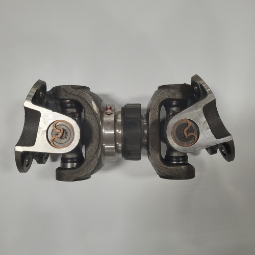
VersaMill Driveshaft Grease
The VersaMill has custom driveshafts that will need to be greased periodically. The lubrication points are located in multiple locations on the driveshaft (see image below).
The recommended greasing interval is once every 500 Hours of operation.
The recommended grease type is shown below:
- Spicer Ultra-Premium Synthetic Grease
- Chevron Ultra-Duty EP-2
- Any compatible Lithium based grease meeting NLGI Grade 2 and ASTM D4950 LB Specifications
Grease Line
High pressure grease line significantly reduces chances of blown out lines to ensure moving parts stay greased.

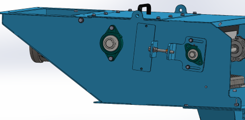
Gap Settings at Startup & Roll Re-Alignment
Your mill is equipped with roll adjustment points.
These are located on the front of the machine – see image below.
Setting and keeping the roll gaps is essential to target your desired grind. Keeping rolls in parallel is essential for proper wear on the rolls and consistent output.
For additional information on the following sections, see Page 9.1 for Feed Mills and large Brewery mills. See Page 9.2 for the MicroMill and 6x6 mills.
SECTION I: Starting up the mill
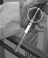
SECTION II: Zeroing the Rolls
SECTION III: Paralleling the Rolls
Stickers like this can be found on the adjustment points of your mill.
Roll Re-Alignment for Feed Mill
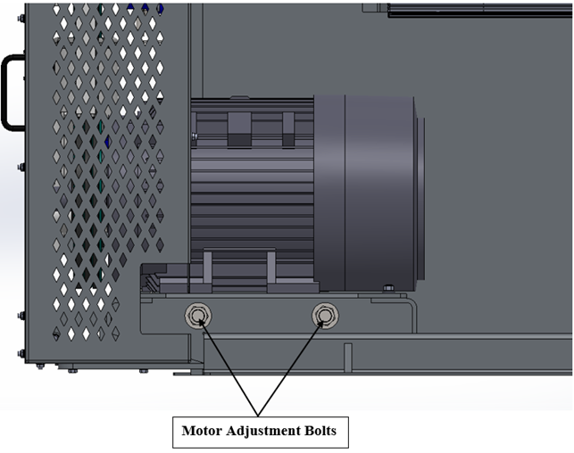
SECTION I: Starting up the mill
The in-feed should be shut off with no material entering the rolls. The guide arms or T.A.S. below the in-feed should be set just slightly from touching the rolls. The T.A.S. adjustment bolts can be found on the side of the roller mill.
RMS suggests beginning with a roll gap of 0.100”, or approximately 1 revolution of the adjustment bolt.
You can now start up the mill. Once started, move adjustments into desired gap setting then slowly feed the machine until the max amps or capacity desired is reached.
Note: DO NOT over amp your motors or motor failure will occur. If over amp occurs, reduce the feed of material until you are back under the max amperage.
SECTION II: Zeroing the Rolls
Parallel and zero the rolls approximately once a week, or whenever the desired material cannot be obtained.
Important: The machine must be empty before adjusting rolls.
-
With the machine running, stop the flow of material going into the machine.
-
Locate the roll adjustment points.
-
There are (2) adjusting hex bolts per set of rolls. Turning either bolt clockwise closes the rolls on the side turned. counter-clockwise rotation opens the rolls on the side turned.
-
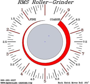
Start by turning the left bolt clockwise until you hear the rolls just start to nick each other. Move pointer to zero when the rolls start to nick.
-
Turn the bolt back counter-clockwise to 8 on the reference sticker then move in clockwise to 5 (Any time you are moving the adjustment out (counter-clockwise) you must move past your target number and bring it back in to take the backlash out of the adjustment screw).
-
Move the adjustment in (turn clockwise) and repeat steps 4 and 5 using the 2 on the reference sticker as your starting point.
-
Once again, turn the bolt clockwise but stop turning just short of where the rolls start to nick. The idea is to leave the bolt set in the direction of closing the rolls, but just shy of where the rolls nicked.
-
Repeat the process with the bolt on the right side.
-
Continue doing this adjustment on both sides at least three (3) times. This ensures the rolls are precisely parallel.
-
All pointers can now be reset to zero.
Section III: Paralleling the Rolls
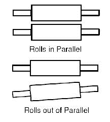
Rolls have been knocked out of alignment (out of parallel).
Follow the same procedures listed in Section II if the following events are observed:
• A foreign object is known to have been run through the mill.
• During normal re-alignment, you find that you must turn one hex bolt further than the other in order to nick the rolls, indicating that the rolls are out of parallel.
For additional information see our YouTube video! How to Properly Parallel and Zero Rolls
Roll Re-Alignment for Micromill & 6x6 Brew Mill
SECTION I: Starting up the mill
The in-feed should be shut off with no material entering the rolls.
RMS suggests beginning with a roll gap of 1/8”, or approximately 2 revolution of the adjustment bolt.
You can now start up the mill. Once started, move adjustments into desired gap setting then slowly feed the machine until the max amps or capacity desired is reached.
Note: DO NOT over amp your motors or motor failure will occur. If over amp occurs, reduce the feed of material until you are back under the max amperage.
SECTION II: Zeroing the Rolls
Parallel and zero the rolls approximately once a week, or whenever the desired material cannot be obtained.
Important: The machine must be empty before adjusting rolls.
-
With the machine running, stop the flow of material going into the machine.
-
Locate the roll adjustment bolts and loosen the set screw on both the right and left adjustment pointers.
-
Use the provided allen wrench to turn the right adjustment bolt (Socket Head Cap Screw) counter-clockwise until you hear a deep rumble. This is the sound of the front roll touching the rear roll.
- Note: If you hear a high pitch sound continue to turn the screw counter-clockwise until a deep rumble is heard. The high pitch sound is likely the front roll touching a V-Block.
-
While hearing the deep rumble, move the loosened pointer to 0.
-
Once the pointer is at the zero value, use the provided allen wrench to turn the right adjustment bolt clockwise to 24 then counter clockwise to the 17.
-
Use the provided allen wrench to turn the left adjustment bolt counter-clockwise until you hear a deep rumble.
-
While hearing the deep rumble, move the loosened pointer to 0.
-
Once the pointer is at the zero value, use the provided allen wrench to turn the right adjustment bolt clockwise to 24 then counter clockwise to the 17.
-
Repeat this process on both the right and left adjustment bolts until the deep rumble is heard when the pointer is at zero without the need of hand turning the pointer. This may take multiple times depending on how out of parallel the movable roll is.
-
The movable (front) roll is now parallel to the stationary (rear) roll. Tighten the set screws on the adjustment pointers.
Section III: Paralleling the Rolls
Rolls have been knocked out of alignment (out of parallel).
Follow the same procedures listed in Section II if the following events are observed:
• A foreign object is known to have been run through the mill.
• During normal re-alignment, you find that you must turn one hex bolt further than the other in order to nick the rolls, indicating that the rolls are out of parallel.
Roll Corrugations
You will eventually need to get your rolls re-cut or re-corrugated. Roll sharpening can lessen your roll life, but RMS uses specialized techniques to maintain your roll diameter, therefore allowing your rolls to be re-sharpened multiple times.
When is it time to have your rolls sharpened?
Indications of rolls being dull:
- Can’t pull amps; meaning the rolls are not sharp enough to grab the material and pull it through, they lack traction.
- Material is building up on top of the rolls at a faster rate than when rolls were first installed.
- Machine is losing capacity and not processing the same amount of material as when rolls were first installed.
- Typically, the interval between roll sharpening/exchanges is constant; meaning that if you ran (x) amount of material through the mill (y) months ago and you needed a roll sharpening, then you can assume at the same amount of material you will need to sharpen the rolls again in (y) months.
- Visual inspection of rolls shows bald spots on rolls where corrugations are worn down.
Roll Maintenance
Factors to consider which affect roll sharpness:
- Rolls should be fed uniformly to maximize machine efficiency.
- Rolls being out of parallel will increase roll wear. Your facility should have a program in place to regularly zero and parallel your rolls, to ensure they are in parallel. If you use your machine daily, parallel the rolls weekly.
Note:
Roll sharpening MUST be performed by RMS Roller-Grinder or warranty will be void.
RMS utilizes specialized rolls and processing techniques that are specific to a roller mill in this application.
Roll Removal
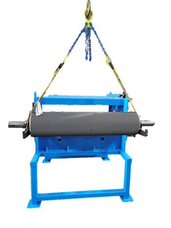
Qualified personnel must ensure that they are lifting the rolls using the proper equipment and lifting procedure.
It is recommended to lift the roll using a lifting strap that has a rated capacity that is higher than the overall weight of the roll.
The image below shows the recommended procedure for lifting a roll.
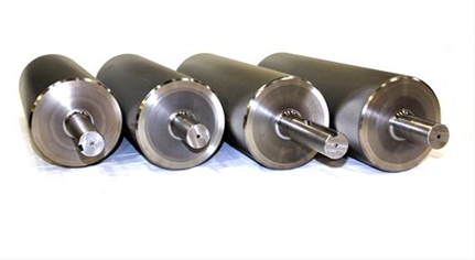
A table showing the roll weights is shown below.
| Roll Size | Roll Weight | Roll Size | Roll Weight |
|---|---|---|---|
| 3x3 | 10 Lbs. | 12x24 | 780 Lbs. |
| 6x6 | 50 Lbs. | 12x30 | 990 Lbs. |
| 9x6 | 150 Lbs. | 12x36 | 1,200 Lbs. |
| 9x12 | 250 Lbs. | 12x42 | 1,350 Lbs. |
| 9x18 | 360 Lbs. | 12x52 | 1,700 Lbs. |
| 9x24 | 480 Lbs. | 12x72 | 2,350 Lbs. |
| 9x30 | 600 Lbs. | ||
| 9x36 | 730 Lbs. |
V-Belt Tensioning and Pulley Alignment Guidelines
Warning:
These guidelines are general in nature and are not intended to be “instructions”.
It is the operators’ responsibility to educate themselves using reference material readily obtainable from “power transmission industry” sources.
It is very important that no one be allowed to apply the following guidelines without adequate experience in the field of V-Belt power transmission.
Most importantly, the operator must have knowledge and experience concerning the inherent danger involved when working on V-Belt power transmission equipment.
RMS Roller-Grinder
assumes no liability for the use of the following guidelines.
V-Belt Tensioning Guidelines:
Important:
Always make sure the rolls are fully closed before tensioning V-Belts. If belt tension is set with the rolls open, the belts will be too loose once the rolls are closed. This may result in belt failure or motor shaft/bearing failure.
V-Belts should be tensioned only as tight as required to prevent the belts from slipping. There are two signs of excessive belt slippage:
- Belts “squeal” for more than one second on start up.
- Belts are hot after only a short time of running.
(New belts will run warm during initial break-in, and may need to be re-tightened after a few hours running.)
Pulley Alignment Guidelines:
Important:
Make sure the rolls are fully closed before proceeding with the following instructions.
-
Motor Pulley Alignment: Start by making sure the motor pulley is “in line” with the roll pulley(s). Place the straight edge against the face of the roll pulley and extend it across to just below or above the motor pulley. By slightly turning the roll pulley, with the straight edge held tightly against and rotating with the roll pulley, the straight edge should just clear the motor pulley, or be within 1/8” either in or out of the just clearing. If the motor or pulley is more than 1/8” in or out it should be repositioned on the motor shaft so that it is “in line”.
-
Motor to Roll Parallel Alignment: First make sure the belts are tight but not too tight. Place the straight edge against the face of the motor pulley and extend it across to just below or above a roll pulley. By slightly turning the motor pulley, with the straight edge help tightly against and rotating with the motor pulley, the straight edge should just clear the roll pulley. Use the 2 motor adjusting rods in the back of the machine to get “in line”. If the belts are not tight enough yet, finish tightening the belts by turning BOTH rods clockwise the same amount.
Belt Tensions
Belts Stretch over their lifespan. Therefore, belts should be checked periodically for proper tension and alignment, especially when the mill is first used or if new belts are installed.
How to Adjust the Tension and Alignment
-
To maximize v-belt life and optimize your machine’s performance make sure the proper belt tension is maintained.
-
Adjust belt tension only when your rolls are in the position that they run the majority of the time
-
V-Belts should be tensioned only as tight as required to prevent belts from slipping. If the belts start to slip, simply tension more. But DO NOT over tighten the belts!
-
If the belts are over tensioned, it may result in shaft failure or motor failure.
-
Lastly, to ensure the best performance out of your belts, and the longest life, you must make sure they are operating within the recommended load limitations. You must monitor the motor amps while the machine is in operation to ensure the work is being evenly distributed between your sets of rolls.
Warning:
Never remove the belt guard while the machine is in operation!
For additional information see our YouTube video! How to set belt tension on your Roller Mill
Belt Alignment
Belt alignment, like belt tension, is critical. Improper alignment of the motor pulley to the roll pulley(s) can result in reduced horsepower transfer, belt failure, and/or motor failure.
Figure 8. Misaligned pulleys vs. aligned pulleys.
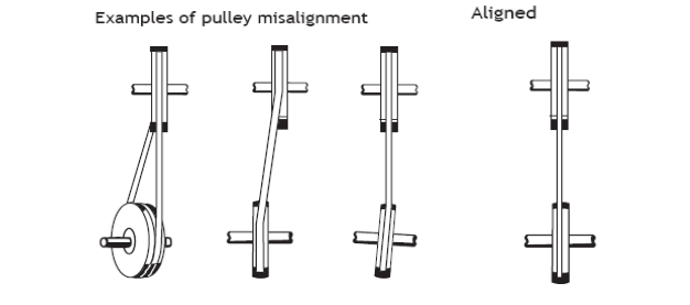
There are two aspects of proper motor pulley alignment:
-
The motor pulley must be positioned properly on the motor shaft. If the mill was ordered with a motor(s), the pulley alignment should be correct.
-
The motor shaft must be parallel to the roll shaft, i.e., the motor should not be cocked. Using a straight edge, make sure the motor is not cocked due to belt tension. Place the straight edge flat against the face of the motor pulley, but so it just misses the roll pulley. Now raise or lower the straight edge at the roll pulley end and check to see whether the straight edge just touches the face of the roll pulley. Adjust the motor mount threaded rods accordingly.
Important:
For the final adjustment, the threaded rod furthest from the belts should not be pulling the motor; it must push the motor back toward the mill to overcome the belt tension’s tendency to “cock” the motor.
For more information on Belt Tension and Alignment in video form visit: https://www.rmsroller-grinder.com, under Links, then Industry Links
Feed Roll
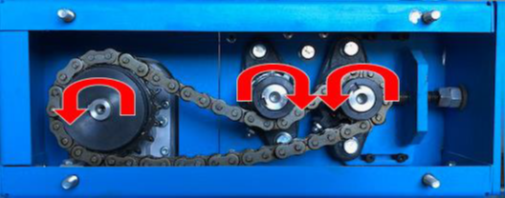
Feed Roll Rotation
While standing on the right side of the machine the feed roll should spin clockwise.
Feed Roll Speed
The feed roll speed is designed to be variable. This allows you to specify the amount of product being fed to the rolls.
Wiring the Feed Roll
The feed roll is powered by either a one or two horsepower motor. This motor is powered and controlled from a variable frequency drive (VFD). The VFD should be interlocked to the main grinding motors such that it cannot be turned on unless the main motors are energized.
Flooding the Rolls
The operator must take care to avoid over-feeding the rolls. Over-feeding the rolls can cause the main motor amps to exceed recommended allowable amps and may result in obstructing product flow altogether, plugging the mill.
Gearbox Lubrication Guidelines
For general temperatures, the greasing guidelines and grease types recommended in the lubrication section are applicable. If, however, the mill environment temperature varies into the extreme hot or cold, a synthetic oil is preferable. RMS recommends Lubriplate Syn Lube 220 L0975-057. The correct lubricant is important, as without the appropriate oil/grease, the gearbox could cease to function properly.
Replacement Bearings:
(1) 4-Bolt 2 7/16" Flange Ball Bearing You can order directly from RMS!
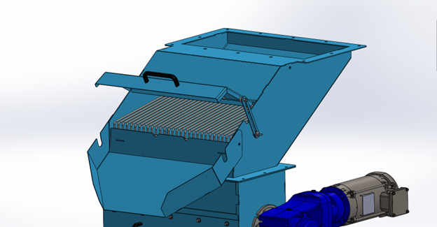
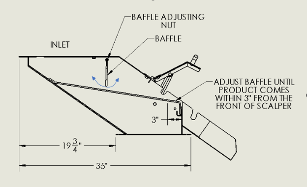
Adjusting the Scalper:
A properly adjusted scalper is important for maintaining grind efficiency and mill safety. You adjust your scalper by varying the angle of the baffle (a rod with a steel flap attached). The baffle is used to constrict the amount of grain flowing over the scalper grate, which consists of long, thin metal rods that sift foreign materials from your pre-grind product.
Adjust the baffle until product comes within 3” of the scalper discharge, as shown in Figure 14. This sifts out the maximum amount of foreign material while ensuring minimal product waste.
Figure 14. How to adjust an RMS Gravity Scalper.
Electrical Instructions
Electrician
RMS is happy to work with your electrician to answer any questions pertaining to wiring the motors and other electrical components on your mill. Our engineers can work with the electrician to make sure everything functions properly. Following are some important electrical guidelines.
Main motor start up sequence:
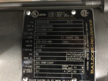
- Consult the wiring legend on the motor as in the photo below.
Motor nameplates include wiring legends.
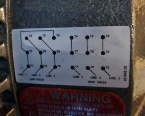
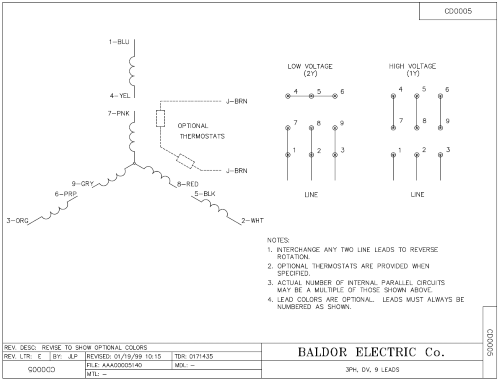
- Find your Motor Startup sequence!
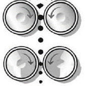
Motor rotation:
• When looking at the left side of the machine, the motor should be spinning in a counter-clockwise rotation. This is also true of the right side of the machine.
Rolls should spin inwards when motors are spinning counter-clockwise.
IMPORTANT:
Any electrical work should be completed only when power sources to each motor have been disabled and motors have cooled down!
Check and clean motors at least monthly to ensure they are free from contaminates. This ensures the motors are able to adequately cool themselves and avoid overheating.
Interlocking
Interlocking the electrical components on a roller grinder is one of the most important steps when installing a machine.
You must interlock the main grinding motors to the downstream take away equipment, an auger or chain disk conveyance system for example, to prevent them from starting if those downstream components are not energized.
This is critical to ensure that the roller grinder shuts off if the one of the components downstream stops running for any reason.
Amp Meter Box
We highly suggest you install an amp meter box on your mill to prevent over amperage of motors, loading to motor failure, or overload.
Small Motor Overload Protection
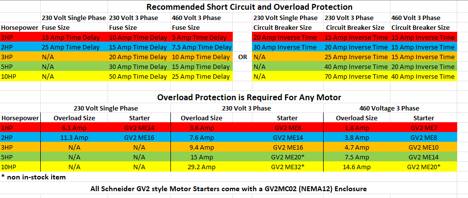
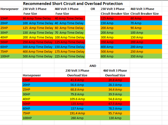
Large Motor Overload Protection
Motor Wiring Diagram and Starting Sequence
Note: Motor wiring orientation is determined upon whisch set of rolls draws the amps from each motor, not the physical location of the motor on the mill!
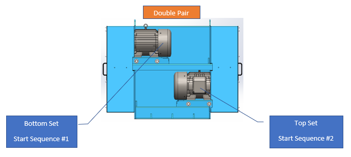
Double Pair starting sequence
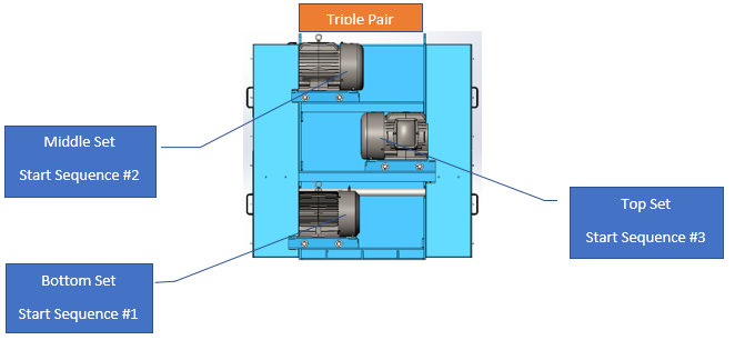
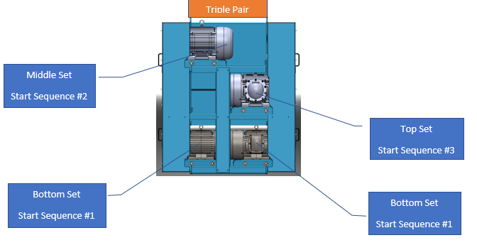
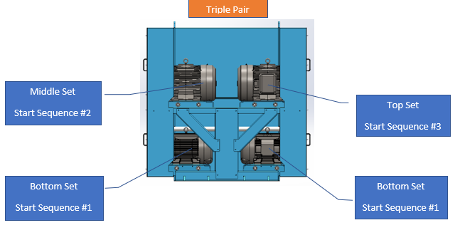
Triple Pair starting sequence
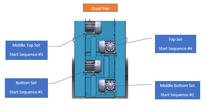
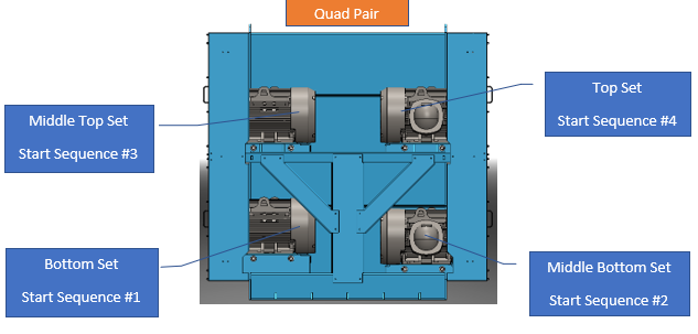
Quad Pair starting sequence
Find the motor configuration of your model and follow the diagrammed procedure!
Double Pair Motor Start Procedeure
Confirm the Motor Configuration and follow the diagrammed procedure!
Triple Pair Motor Start Procedeure
Confirm the Motor Configuration and follow the diagrammed procedure!
Quad Pair Motor Start Procedeure
Confirm the Motor Configuration and follow the diagrammed procedure!
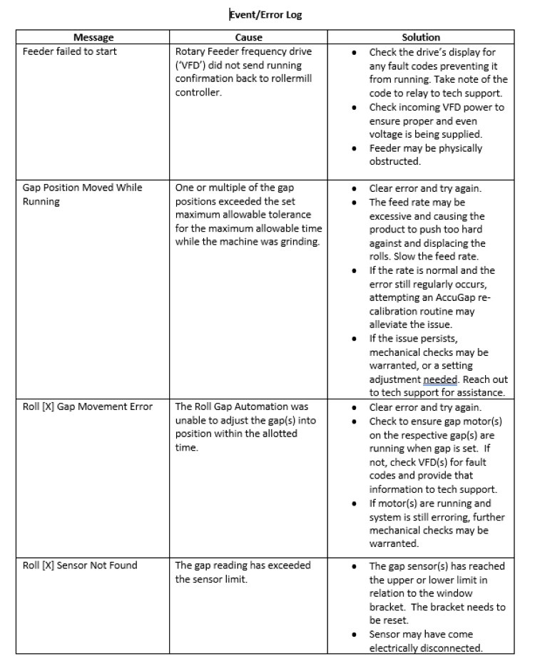
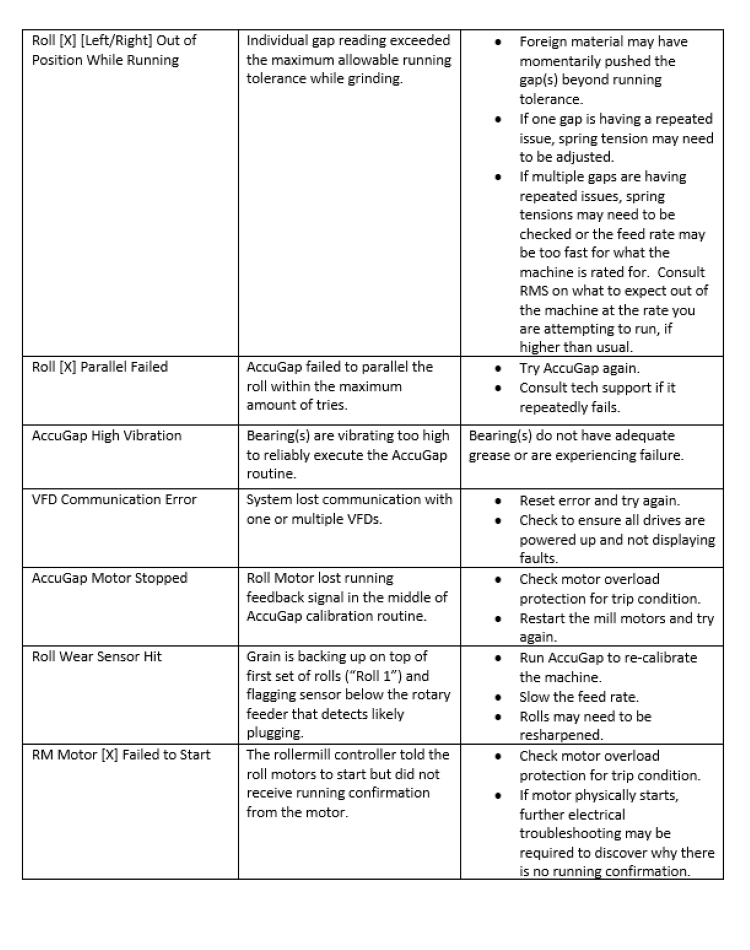
Control Panel Error Log
The table below shows common messages/errors that may appear if you are using an Easy Automation Control Panel.
Use this table to see the cause and possible solution to each error message.
Brew Mill Installation
Find the assembly instructions HERE !
Find the motor starter wiring information HERE !
Installing a machine on a stand:
If the machine is installed on a stand it is critical that this stand is built to handle the overall weight of the machine and product that will be in the machine. As a general rule of thumb the stand should be built will a 1.5 to 1 safety factor.
It is recommended to anchor the brew mill stand using Grade 5, 1/2" concrete anchors at a minimum thread length of 1". Anchor depth may vary based on application. Anchors should be torqued to approximately 40 ft. lbs.
An example of brew mill stand anchor locations is shown below:
Bolting machine to the ground:
Concrete anchor bolts must be used when the machine is being installed on concrete. If the machine is being installed on a steel platform grade 5 bolts or better should be used. Machines should be checked for level, no matter where they are installed, before being secured.
It is recommended to anchor the brew mill stand using Grade 5, 1/2" concrete anchors at a minimum thread length of 1". Anchor depth may vary based on application. Anchors should be torqued to approximately 40 ft. lbs.
An example of brew mill anchor locations is shown below:
To prevent dust leaks:
After the machine is in place and bolted, the seams between each flange should be sealed with silicone caulk, to ensure it stays dust tight.
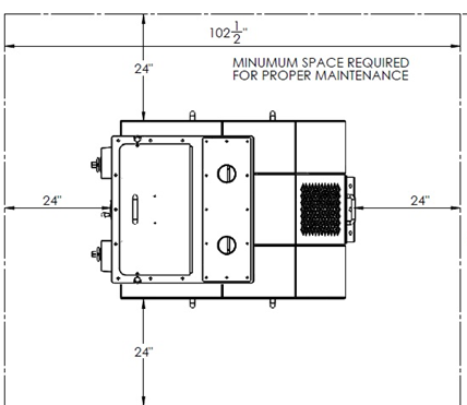
Clearances around the machine:
It is important to take into consideration the space that is required for roll changes and routine maintenance work when deciding where to place your machine. Call RMS for recommended clearances.
Feed Mill Installation
Find the Pre-Start-Up Checklist HERE !
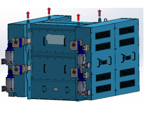
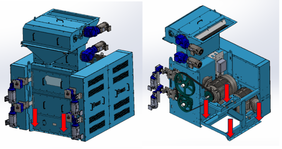
Lifting the machine
When installing a machine, it must be lifted in the proper way to ensure safety and eliminate the potential of damaging the machine.
The machine can be lifted from the bottom using a forklift. The forks should be spread out as close to the side plate of the mill frame as possible to ensure stability.
See image below:
The machine can also be lifted from the top using the lifting eyes that are built into the mill frame. Proper rigging must be used to ensure the load is lifted vertically at each attachment point. The use of a lifting/spreader beam is recommended to reduce the likelihood of damaging the machine.
See image below:
Note: Forklift must have a rated capacity that is higher than the overall weight of the equipment being lifted.
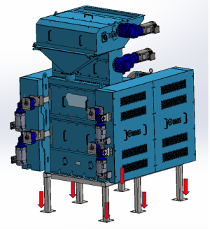
Installing a machine on a stand
If the machine is installed on a stand it is critical that this stand is built to handle the overall weight of the machine and product that will be in the machine. As a general rule of thumb the stand should be built will a 1.5 to 1 safety factor.
It is recommended to anchor the mill stand using Grade 5, 1/2" concrete anchors at a minimum thread length of 1-1/2". Anchor depth may vary based on application. Anchors should be torqued to approximately 40 ft. lbs.
An example of mill stand anchor locations is shown below:
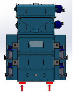
Bolting machine to the ground:
Concrete anchor bolts must be used when the machine is being installed on concrete. If the machine is being installed on a steel platform grade 5 bolts or better should be used. Machines should be checked for level, no matter where they are installed, before being secured.
It is recommended to anchor the mill stand using Grade 5, 1/2" concrete anchors at a minimum thread length of 1-1/2". Anchor depth may vary based on application. Anchors should be torqued to approximately 40 ft. lbs.
An example of mill anchor locations is shown below:
To prevent dust leaks:
After the machine is in place and bolted, the seams between each flange should be sealed with silicone caulk, to ensure it stays dust tight.
Clearances around the machine:
It is important to take into consideration the room you will require for roll changes and routine maintenance work when deciding where to place your machine. Call RMS for recommended clearances.
Vertical Auger
| Motor Location | Motor Size |
|---|---|
| Horizontal Auger | 1HP |
| Vertical Auger | 2HP |
| Belt Location | Quantity | Belt Size | Belt Tension |
|---|---|---|---|
| Horizontal Auger | 1 | A50 | 1.5 - 1.6 Lbs. |
| Vertical Auger | 2 | A47 | 2.4 - 2.5 Lbs. |
| Bearing Location | Bearing Type | Bearing Qty. |
|---|---|---|
| Horizontal Auger | 1" Square 4-Bolt Ball Bearing | 3 |
| Vertical Auger | 1-3/8" Square 4-Bolt Roller Bearing | 1 |
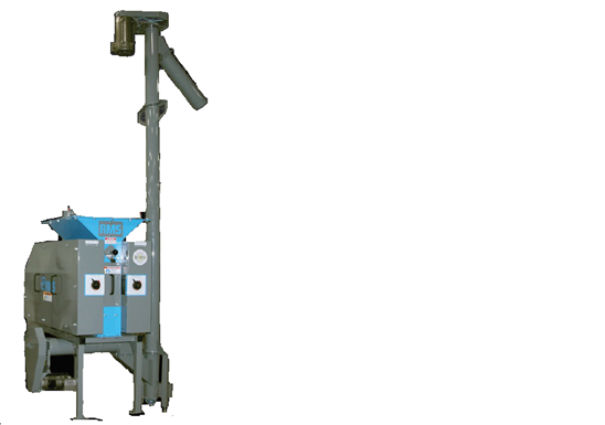
Installation
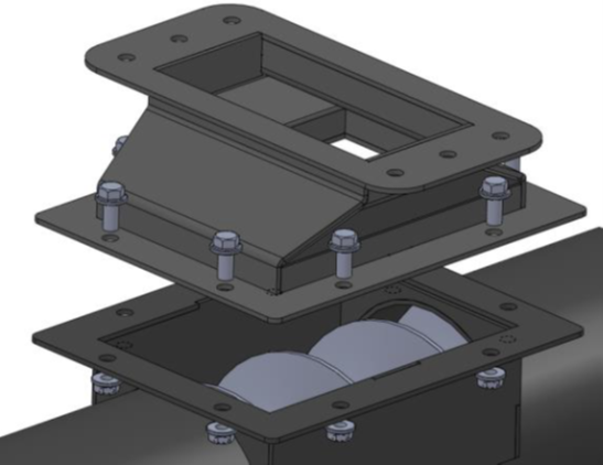
Installing Horizontal Portion of Auger to Mill:
Position the horizontal section of the auger under mill, so the mounting flange of the transition discharge lines up with the mounting flange on auger, as depicted in image below. RMS provides a strip of adhesive backed foam seal to be used between the two flanges to make the joint dust tight. Secure the auger to the mill with 3/8” flange bolts and nuts, as shown in image.
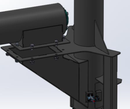
Installing Vertical Portion of Auger to Horizontal Section:
Position the vertical section of the auger under the horizontal section so the mounting flanges of both sections are aligned, as depicted in image below. Use the provided foam seal between the two flanges to make the joint dust tight. Secure the two sections together using the 3/8” flange bolts and nuts, as shown in image. A lifting bracket has been provided on the vertical section to aid in positioning the vertical section.
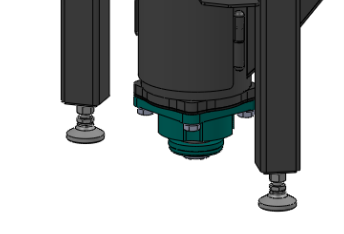
Leveling Vertical Auger:
Adjust leveling feet on the bottom of the vertical auger legs, then secure in place by tightening the lock nuts.
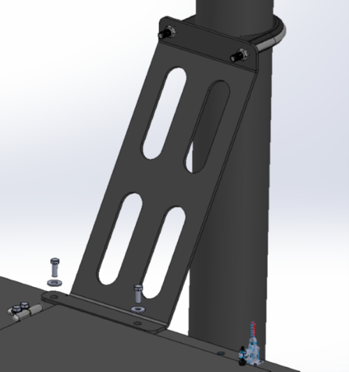
Securing Vertical Auger to Mill with Support Bracket:
Clamp the support bracket to the vertical tube with the “U”- bolt clamp, and to the mill with two 3/8” bolts and nuts. Depending on the overall height of the vertical auger, additional support may be needed to secure the vertical section.
For additional information on assembling multiple sections of auger together, see Assembly Instructions
Lubrication
All bearings should be greased following the greasing schedule mentioned below. Before greasing, grease zerks should be cleaned to prevent contaminants from entering the bearing.
The bearings on the vertical auger cannot be over greased. Any excess grease will purge through the seals on the front and rear of the bearing. Grease the bearings on the auger once per month, located on the horizontal section (two) and vertical section (at top). Grease these three ball bearings with 1-2 pumps monthly. The roller bearing is the bottom bearing on the vertical section. Grease the roller bearing with 2-3 pumps monthly. Note that a small amount of grease at frequent intervals is preferable to a large amount at infrequent intervals.
Note: Bearings from RMS come greased and ready for operation. Bearings directly from the manufacturer should be greased to purge.
Note: RMS suggests any lithium-based NLGI #2 grease such as “Feedmillube” which can be purchased through RMS or online at Feedmillube.com
Belt Tension
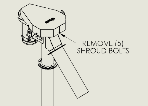
Adjusting Belt Tension
- Before adjusting belt tension, the shroud around the belts will need to be removed. Remove the (5) bolts around the outside of the shroud, and lift the shroud up and off of the tabs.
- Next, crack the (4) lock bolts loose that are holding the motor in place. >Note: Do not completely remove these bolts as the motor could fall.
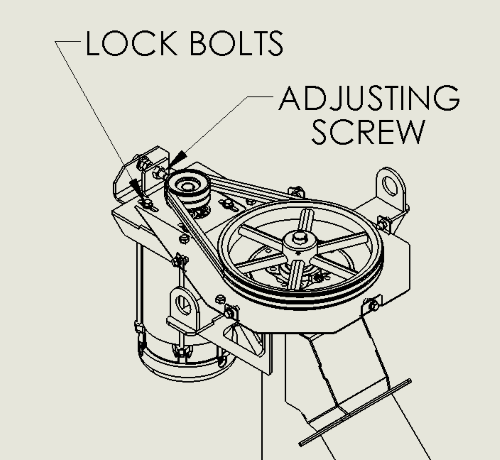
- Adjust the belt tension by turning the adjusting screw counter-clockwise to increase tension, and clockwise to decrease tension. Once desired tension has been achieved, tighten the lock bolts and reinstall the shroud.
For additional information on tensioning belts, see Belt Tension.
Electrical Instructions
RMS strongly suggests you hire a licensed electrician for the initial install of the electrical components.
For additional wiring information, consult the wiring legend on the motor as in the photo below.
Motor/ Auger Rotation
The motors for both the horizontal section and the vertical section should spin counter-clockwise. Both of these directions are determined when looking at the shaft side of the motor. (See image below). This means the motor for the horizontal auger needs to spin counter-clockwise, and the motor for the vertical auger needs to spin clockwise.

Important: Check and clean motors at least monthly to ensure they are free from contaminates. This ensures the motors are able to adequately cool themselves and avoid overheating.
To avoid serious injury: Always complete this task when all power sources to each motor have been disabled and motors have cooled down!
Interlocking
Interlocking the electrical components on a roller grinder is one of the most important steps when installing a machine. You must interlock the main grinding motors to the downstream take away equipment. In this case, the vertical auger should be interlocked to the mill to prevent the mill from starting if the auger is not energized. This is critical to ensure that the roller grinder shuts off if the one of the components downstream stops running for any reason.

View the AccuGap Manual
MicroMill
| Model | Cracking Capacity | Motor Size |
|---|---|---|
| 3x3 MicroMill | 500# per hour | 1/3HP Single Phase |
Lubrication
Bearings
The 3x3 mill features greaseless bearings. These are sealed bearings and do not require regular greasing. Tips for longevity of these bearings.
- A visual inspection to ensure bearings are functioning as they should.
- Monitor temperature of the bearings during operation. If a bearing is noticed to be overheating or carrying an excessive amount of heat during operation, please contact the RMS Service team.
Chain and Sprockets
The drive system of the 3x3 mill uses a chain and sprocket configuration. This should be a low-wear area; however, if the chain or gear drive system begins to make noise or becomes a concern, a high-quality chain lube can be applied to the chain and sprockets.
Motor Rotation
When looking at the left side of the machine, the motor should be spinning in a counterclockwise manner. This should ensure the rolls are spinning inwards towards each other. See photo below for reference.
Important: Check and clean motors at least monthly to ensure they are free from contaminates. This ensures the motors are able to adequately cool themselves and avoid overheating.
Interlocking
Interlocking the electrical components on a roller grinder is one of the most important steps when installing a machine into a grain handling system. You must interlock the main grinding motors to the downstream take away equipment, an auger or chain disk conveyance system for example, to prevent them from starting if those downstream components are not energized. This is critical to ensure that the roller grinder shuts off if one of the components downstream stops running for any reason. RMS will not be responsible for warranty claims should you fail to interlock your mill with upstream or downstream equipment and failure takes place.
If you’re using the mill as a standalone machine, not tied into a grain handling system, interlocking is not necessary.
MicroMill Installation
Installing a machine on a stand:
The 3x3 mill comes with a mill stand as a standard feature. If the machine is installed on a stand not supplied by RMS, it is critical that this stand is built to handle the overall weight of the machine and product that will be in the machine. As a general rule of thumb, the stand should be built with a 1.5 to 1 safety factor. The estimated weight of a 3x3 mill is 200 pounds.
Bolting machine to the ground:
Concrete anchor bolts must be used when the machine is being installed on concrete. If the machine is being installed on a steel platform, grade 5 bolts or better should be used. Machines should be checked for level, no matter where they are installed, before being secured.
To prevent dust leaks:
If used in conjunction with a grain handling system, any connections to and from the mill should be sealed with silicone calk to keep dust build up as minimal as possible.
Scalper Assist
Scalper Assist Motor Rotation
While standing on the right side of the machine, the scalper assist shafts should spin clockwise.
Scalper Assist Motor Wiring and Speed Reference
The Scalper Assist is powered by a two horsepower motor. The motor is started and controlled by a custom parameter Variable Frequency Drive (VFD). The VFD that controls the Scalper Assist is tied into the output of the Feed Roll VFD. This prevents the Scalper Assist from starting when it shouldn’t and allows the Scalper Assist cleaning speed to proportionally increase as the Feed Roll Speed increases. This VFD also offers a feature that decreases the motor power as it sees a blockage to prevent breakage.
Replacement Parts:
(1) 2-Bolt 1-1/2" Flange Ball Bearing
(2) 2-Bolt 1" Flange Ball Bearing
(4) Scalper Paddles
(2) ANSI #80 Roller Chain
You can order directly from RMS!
Flex Auger System
View the Flex Auger Manual here!
2-3/8" Chain Disk System
View the Chain Disk Manual here!
4" Chain Disk System
View the Chain Disk Manual here!

Frequently Asked Questions
What if my main motor breaker trips?
-
Is the breaker sized correctly for the motor being used?
- Look at the nameplate on the motor and find the correct breaker size.
- Verify that the breaker is sized correctly for peak motor start-up. It needs to handle the maximum voltage pull from the motors.
-
Is there material in the rolls?
- Rolls should turn freely by hand. If not, first turn off all power supply to the mill. Then open the front cover and clean out any product from between the rolls.
-
Is there a foreign object in the rolls?
- Rolls should turn freely by hand. If not, first turn off all power supply to the mill. Then open the front cover and clean out any product from between the rolls.
-
Is the motor being over-worked?
- Open the roll gap on the set of rolls that the over-worked motor drives. This will allow grinding work to move to another set of rolls, distributing the work between motors.
What if I can’t get my desired grind capacity?
-
Are the rolls getting dull?
- Call RMS 605-368-9007 to schedule a stop-and-check or a roll exchange.
-
Does the motor amperage-pull fluctuate?
- Motors should pull roughly the same amperage, within 5.00 amps of each other. If your motors are fluctuating more, note the fluctuation and call RMS to schedule a roll exchange.
-
Is the top set of rolls not pulling any amps?
- Check the roll gap. If the top rolls aren’t pulling any amps, they probably aren’t processing material.
-
Are the roll gaps set to give maximum output?
- Adjust roll gaps as necessary.
What if my bearings are running above normal operating temperature?
-
Have the bearings been greased?
- If not, grease the bearings. Refer to the lubrication section of this manual for a greasing schedule and recommended grease type.
-
Is the bearing still running abnormally hot after greasing?
- Give RMS a call at 605-368-9007. Your bearing may be going bad.
-
What if my bearing is also making a whistling noise?
- Give RMS a call at 605-368-9007. Your bearing may be going bad.
What if my belts are Squealing?
- Verify the following:
- Belts are correctly tensioned.
- Pulleys are aligned.
- Belts are in good condition.
- Pulleys are in good condition.
- Belts are tensioned using the automatic motor base adjustment.
What if I can’t get my target material anymore?
- Visually inspect the rolls and make sure no hard debris has gone through the rolls and left ‘scars’ in the rolls.
- Call RMS 605-368-9007 to determine if a roll change is needed.
- Move the rolls in to zero, are they touching?
- If not, you need to re-zero the rolls.
Why is there a high pitched noise coming from my machine?
- Our grinders contain a part that is called a V-Block that sits directly on top of the rolls to block any grain from getting around the rolls. The V-Block is installed with as tight of a tolerance as possible to ensure the proper seal. After a few hours of run-time, the rolls will wear into the V-Block and the noise will subside.
Manufacturer Contact Information
| Company: | Part: | Contact phone: |
|---|---|---|
| Leding Lubricants | Automatic Grease System | 479-474-9144 |
| Electro-Sensors | Bearing Monitoring Sensors | 800-328-6170 |
Parts and Services
Recommended Optional Parts:
RMS Roller Grinder strongly suggests all of our customers keep an extra set of belts on hand.
This is because belts will wear over time. If by chance you do not have an extra set, and your belts happen to wear out, or burn up in the event of a failure in your take away system;
What could have been just downtime to change out belts, will end up stopping your production and increasing your costs to have belts overnight. It is to your advantage to keep these on hand.
RMS Roller Grinder also encourages customers to keep an extra set of bearings on hand.
If a foreign object was by chance to get into your rolls and cause a bearing to fail the excess vibration on the roll may cause the other bearing to fail as well.
It is to your advantage to keep an extra set of bearings on hand.
Services
-
Roll Exchange Program
- RMS will provide appropriately sized rolls for you as long as you own your mill.
- There is no need to have extra rolls lying around not making you any money.
- We come to your facility and change out your rolls.
- If you prefer to change out your own rolls we also have the ability to deliver sharp rolls to your facility.
- Our service technicians will work around your production schedule.
- We can group you in with other customers in the area, to help reduce your costs.
-
Machining
- Supply Replacement rolls that are ISO 9007:2000 certified and dynamically balanced.
- RMS sells replacement solid Cast Iron Rolls, as well as Steel.
- RMS offers sharpening and replacement of rolls.
- Roll sharpening to the customer's specifications.
- Recommend roll corrugation to meet the needs of your operation.
- RMS also offers a fully equipped test lab, with ability to test your product to ensure you are maintaining your target particle size.
- Maintain Roll diameter.
- Roll balancing.
- Shaft repair and replacement of bad shafts.
-
On-site Training and Consultation
- Safety
- How to operate your machine at maximum efficiency
- Machine maintenance *Custom training also offered. Let us know what you need to learn and we will be more than happy to assist you with your operations needs.
1. Governing Terms. These Terms and Conditions of Sale (“Terms”) apply to and govern the sale by RMS Roller-Grinder (“RMS”) of all products (“Products”) that RMS agrees to sell to Buyer and the performance by RMS of all services (“Services”) that RMS agrees to furnish to Buyer, except as otherwise stated in RMS’s Proposal or Sales Order or as otherwise agreed in a written agreement signed by RMS. RMS offers to sell Products and/or Services solely pursuant to these Terms and any acceptance is expressly limited to these Terms. Any additional or different terms proposed by Buyer in any offer, acceptance, confirmation or other document are rejected by RMS and do not bind the parties.
2. Prices. The prices for Products and Services are those contained in RMS’s Proposal or Sales Order or, if there is no Proposal or Sales Order, in RMS’s price list. If the price of fuel, materials or other production items increase, RMS may impose a surcharge for affected Products and Services. Unless the parties otherwise agree in writing, the prices for the Products and Services do not include any taxes, customs duties, brokerage fees, or costs of freight, shipping, packaging, labeling, storage or insurance, which will be paid by Buyer in addition to the prices for Products and Services.
3. Payment. All payments for Products and Services are payable on the terms stated in RMS’s Proposal or Sales Order. If a Proposal or Sales Order does not specify payment terms, all payments for Products and Services are due 30 days from the date of invoice, unless otherwise agreed in writing by RMS. At the request of RMS, Buyer will provide financial information for RMS to assess the credit risk of Buyer. RMS, at any time, may change or withdraw Buyer’s credit or impose security or other arrangements to secure Buyer’s payment. All amounts past due will incur a late charge of 1.5% per month. To secure payment by Buyer, Buyer grants RMS a first priority security interest in all Products sold to Buyer until the date the invoiced amount for such Products has been paid.
4. Title; Delivery. Unless otherwise agreed in a written agreement signed by RMS, all Products are sold FOB, Freight Collect, at RMS’s facility. Title to, and risk of loss of, Products will pass to RMS upon delivery to the carrier at RMS’s facility. RMS will use commercially reasonable efforts to deliver Products or Services on or before the scheduled shipping/delivery date thereof.
5. Inspection. Buyer will have three days after Buyer’s receipt of Products or Services to inspect the Products or Services. Buyer will be deemed to have accepted the Products or Services unless Buyer notifies RMS in writing of any defect within such three-day period.
6. Cancellation. Buyer may not cancel or change an order for Products or Services, except upon the written consent of RMS. If Buyer cancels or changes an order for Products or Services, Buyer will reimburse RMS for all work-in-process, materials, subcontractor costs, vendor costs, internal labor costs, and any other costs of RMS associated with the cancelled or changed order, and will be liable to RMS for lost profits and any other consequential and other damages incurred by RMS as a result of such cancellation or change.
7. Breach. Any one of the following acts by Buyer will be a material breach of these Terms by Buyer: (a) Buyer fails to pay for any Products or Services when due; (b) Buyer fails to accept conforming Products or Services; (c) the filing of a voluntary or involuntary petition in bankruptcy against Buyer, Buyer’s insolvency, or an assignment for the benefit of creditors of Buyer; or (d) Buyer’s failure to provide adequate assurance of performance within ten (10) days after a justified demand by RMS. In the event of a breach, RMS, in addition to all other rights or remedies hereunder or at law or in equity and without liability to Buyer, may terminate its obligations by written notice to Buyer. Buyer will pay all costs, including reasonable attorneys’ fees, incurred by RMS as a result of Buyer’s breach.
8. Limited Warranty. RMS warrants its Products as described in this section.
For a new mill, RMS provides a one year limited warranty, commencing on the date of delivery of the mill to Buyer pursuant to Section 4 above.
This warranty covers the frame, motors, motor mounts, rolls, shafts, bearings, gear boxes, pulleys, fine adjustment assembly, slopes, belt guards, feed roll box, feed roll shaft and idler shaft, warranting that such items will be free from defect in material and workmanship under proper use, service and conditions. This warranty excludes belts, motor mount threaded rods and nuts, and other items not listed in the preceding sentence.
For a roll exchange, RMS provides a 30-day limited warranty, commencing on the date of completion of the roll exchange. This warranty covers the rolls, roll shafts and bearings, warranting that such items will be free from defect in material and workmanship under proper use, service and conditions. This warranty excludes any items not listed in the preceding sentence.
The new mill warranty and roll exchange warranty described above are voided and do not apply if a defect is caused by inadequate maintenance, accident, misuse, neglect, alteration, improper installation or repair, service or repair by someone other than RMS, inadequate machine protection, normal wear and tear, use contrary to any specifications or instructions of RMS, or RMS’s compliance with any designs, specifications or instructions of Buyer.
In the event a Product fails to conform to the new mill warranty or roll exchange warranty described above during the warranty period, RMS will furnish and install a replacement part to replace the defective part, provided however Buyer will reimburse RMS for all labor and travel expenses of RMS, including per diem and hotel, incurred by RMS in installing the replacement part. Except as described in this section above, all Products and Services sold by RMS are sold “AS IS” and with no warranty.
TO THE MAXIMUM EXTENT PERMITTED BY LAW, THIS WARRANTY CONSTITUTES RMS’S SOLE LIABILITY AND OBLIGATION, AND BUYER’S SOLE REMEDY, FOR ANY BREACH OF WARRANTY OR OTHER NONCONFORMITY OF PRODUCTS. THIS WARRANTY IS EXCLUSIVE AND IN LIEU OF ALL OTHER WARRANTIES. RMS MAKES NO OTHER WARRANTY, EXPRESS, IMPLIED OR STATUTORY, INCLUDING ANY WARRANTY OF MERCHANTABILITY, FITNESS FOR A PARTICULAR PURPOSE OR NON-INFRINGEMENT, OR THAT MAY ARISE FROM COURSE OF DEALING, COURSE OF PERFORMANCE OR USAGE OF TRADE. RMS DOES NOT EXTEND THIS WARRANTY, AND BUYER MAY
NOT TRANSFER IT, TO ANY THIRD PARTY.
9. Limitation of Liability. RMS WILL IN NO EVENT BE LIABLE TO BUYER OR ANY THIRD PARTY FOR CONSEQUENTIAL, INCIDENTAL, INDIRECT, EXEMPLARY OR SPECIAL DAMAGES, INCLUDING LOST PROFITS, WHETHER IN AN ACTION BASED ON CONTRACT, TORT OR OTHER LEGAL THEORY, ARISING FROM OR RELATED TO THE TRANSACTIONS CONTEMPLATED HEREUNDER, EVEN IF RMS KNEW OR SHOULD HAVE KNOWN OF THE LIKELIHOOD OF SUCH DAMAGES. WITHOUT LIMITING THE GENERALITY OF THE FOREGOING, IN NO EVENT WILL RMS’S TOTAL LIABILITY ARISING FROM OR RELATED TO THE TRANSACTIONS HEREUNDER (INCLUDING ANY WARRANTY CLAIMS), WHETHER BASED ON CONTRACT, TORT OR OTHER LEGAL THEORY, EXCEED THE TOTAL AMOUNT BUYER PAID TO RMS FOR THE PRODUCTS OR SERVICES GIVING RISE TO SUCH LIABILITY. THE EXISTENCE OF MULTIPLE CLAIMS WILL NOT ENLARGE THIS LIMIT.
10. Acknowledgment. Buyer acknowledges that RMS has set its prices and fees, and has agreed to sell Products and Services to Buyer, in reliance on the limitations of liability, disclaimer of warranties and exclusive remedies set forth in these Terms, and that such provisions form an essential basis of the bargain between the parties, without which RMS would not have agreed to sell Products and Services to Buyer.
11. Indemnity. Buyer will defend, indemnify and hold harmless Seller and its agents, officers, directors and employees from and against any losses, damages, claims, liabilities and expenses, including attorneys’ fees, arising from or related to Buyer’s or Buyer’s customers’ purchase or use of Products or Services, except in the event such losses, damages, claims, liabilities or expenses are caused solely by a breach of RMS’s warranty under Section 8 above, in which case RMS’s liability, if any, will be only to Buyer and will be limited as set forth in Section 9.
12. Software. To the extent any Products or Services contain any software, the following terms apply: (a) RMS or RMS’s licensor retains full ownership, including all patents, copyrights, trade secrets, trademarks and other intellectual property rights, in such software; (b) RMS grants to Buyer a non-exclusive, nontransferable, non-sublicensable, limited license to (i) use internally such software solely in connection with a Product, and (ii) distribute such software that is embedded in a Product (in machine code only) solely as programmed in the Product. Buyer will not engage in unauthorized use or disclosure of software, including any reverse engineering, disassembling, decompiling, copying, modifying, selling or otherwise exploiting the software.
13. Intellectual Property. All products, designs, devices, software, firmware, documents, data, processes, methods and other items that are designed, developed or produced by RMS in connection with any Products or Services are the sole property of RMS and are not “works made for hire” or “commissioned works.” RMS retains all patents, copyrights, trade secrets and other intellectual property rights with respect to any design, process, manufacturing and other technologies used in or resulting from the development or production of Products or Services. Neither Buyer nor any third party will have any right or license in or to any patent, copyright, trade secret or other intellectual property right not expressly granted by RMS in these Terms.
14. Confidential Information. All information Buyer obtains from RMS that Buyer knows or should know is confidential to RMS, including pricing and trade secret information, will remain RMS’s confidential information. Buyer may not disclose such information to any third party.
15. Legal Compliance. Buyer will comply with all applicable laws, regulations and administrative rules governing the purchase and sale of Products, including export and import laws.
16. Assignment. Buyer may not assign any of its rights or delegate any of its obligations under these Terms, whether voluntarily, by operation of law or otherwise, without RMS’s prior written consent, and any purported assignment or delegation without consent will be null and void. In the event Buyer is a corporation or other legal entity, a prohibited assignment will be deemed to have occurred upon the transfer of a majority of shares or other ownership interests in Buyer, whether such transfer takes place in one transfer or successive transfers over time. RMS may assign its rights and/or delegate its obligations under these Terms upon written notice to Buyer. Subject to the foregoing, these Terms will bind each party and its respective successors and permitted assigns.
17. Force Majeure. RMS will not be liable for any delay or failure by RMS to furnish Products or Services due to causes beyond its control, such as acts of God, fires, epidemics, floods, riots, wars, terrorism, labor disputes, governmental actions or the inability to obtain sufficient materials, labor, components, energy, services, facilities or transportation on commercially reasonable terms.
18. Waiver. RMS’s waiver of any right it may have or any default by Buyer will not be a continuing waiver of such right or default or a waiver of any other right RMS may have under these Terms. No waiver by RMS will be effective except pursuant to a writing signed by RMS.
19. Governing Law; Venue. The laws of South Dakota will govern the validity, performance and construction of these Terms and any disputes arising from or relating to these Terms or the transactions contemplated hereunder. All disputes will be subject to the exclusive jurisdiction of the state or federal courts in Lincoln County, South Dakota, and Buyer consents to the personal and exclusive jurisdiction and venue of these courts.
20. Entire Agreement; Amendment. These Terms constitute the entire agreement between Buyer and RMS with regard to the Products or Services and expressly supersede and replace any prior or contemporaneous agreements relating thereto. These Terms may not be superseded, cancelled or amended except in a writing signed by each party. No other act, course of dealing, course of performance or usage of trade will supersede, cancel, modify or amend these Terms. If any provision of these Terms is determined to be invalid or unenforceable, such provision will be enforced to the extent possible and the remaining provisions will remain in full force and effect.